Architectural drawings are drawn
according to a set of conventions,
which include particular views
(floor plan, section etc.), sheet
sizes, units of measurement and
scales, annotation and cross
referencing.Conventionally,
drawings were made in ink on paper
or a similar material, and any
copies required had to be
laboriously made by hand.The
twentieth century saw a shift to
drawing on tracing paper, so that
mechanical copies could be run off
efficiently.
The development of the computer
had a major impact on the methods
used to design and create
technical drawings,
making manual draughting almost
obsolete, and opening up new
possibilities of form using
organic shapes and complex
geometry. Today the vast majority
of drawings are created using CAD
software.
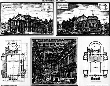
The
Concertgebouw (concert hall) in
Amsterdam,
by Adolf Leonard van Gendt,
illustration published 1888.
An
architectural drawing or architect's
drawing is a technical drawing
of a building (or building project)
that falls within the definition of
architecture. Architectural drawings
are used by architects and others
for a number of purposes: to develop
a design idea into a coherent
proposal, to communicate ideas and
concepts, to convince clients of the
merits of a design, to enable a building
contractor to construct it,
as a record of the completed work,
and to make a record of a building
that already exists.
Sketches
and diagrams
A
sketch is a rapidly executed
freehand drawing, a quick way to
record and develop an idea, not
intended as a finished work. A
diagram may also be drawn freehand
but deals with symbols, to develop
the logic of a design. Both may be
worked up into a more presentable
form and used to communicate the
principles of a design.
In
architecture, the finished work is
expensive and time consuming, so it
is important to resolve the design
as fully as possible before
construction work begins. Complex
modern buildings involve a large
team of different specialist
disciplines, and communication at
the early design stages is essential
to keep the design moving towards a
coordinated outcome.
Architects (and other designers)
start investigating a new design
with sketches and diagrams, to
develop a rough design that provides
an adequate response to the
particular design problems.
There
are two basic elements to a building
design, the aesthetic and the
practical. The aesthetic element
includes the layout and visual
appearance, the anticipated feel of
the materials, and cultural
references that will influence the
way people perceive the building.
Practical concerns include space
allocated for different activities,
how people enter and move around the
building, daylight and artificial
lighting, acoustics, traffic noise,
legal matters and building codes,
and many other issues.While both
aspects are partly a matter of
customary practice, every site is
different. Many architects actively
seek innovation, thereby increasing
the number of problems to be
resolved.
Architectural
legend often refers to designs made
on the back of an
envelope/napkin/cigarette packet.
Initial thoughts are important, even
if they have to be discarded along
the way, because they provide the
central idea around which the design
can develop.
Although a sketch is inaccurate, it
is disposable and allows for freedom
of thought, for trying different
ideas quickly. Choice becomes
sharply reduced once the design is
committed to a scale drawing, and
the sketch stage is almost always
essential.
Diagrams
are mainly used to resolve practical
matters. In the early phases of the
design architects use diagrams to
develop, explore, and communicate
ideas and solutions. They are
essential tools for thinking,
problem solving, and
communication in the design
disciplines. Design is ultimately
about the configurations,
connections, shape, and orientations
of physical forms.Diagrams can be
used to resolve spatial
relationships, but they can also
represent forces and flows, e.g. the
forces of sun and wind, or the flows
of people and materials through a
building.
An
exploded view shows component parts
dis-assembled in some way, so that
each can be seen on its own. These
views are common in technical
manuals, but are also used in
architecture, either in conceptual
diagrams or to illustrate
technical details.
In a
cutaway
view parts of the exterior
are omitted to show the interior, or
details of internal construction.
"The convention of the rough
architectural cutaway can be used to
create a more intense dialogue
between exterior and interior."
(this kind of drawing may be more
visually interesting than the
building it describes). Although
common in technical illustration,
the cutaway is in fact little used
in architectural drawing. It is used
mainly as 3D sketches to illustrate
and expand on formal construction
details.
Sketch
of
a
building.
Diagram
of an Arch
Size
and scale
Main
articles:
Paper size, Engineer's scale,
Architect's scale, and Metric
scale
The
size of drawings reflects the
materials available and the size
that is convenient to transport
rolled up or folded, laid out on a
table, or pinned up on a wall. The
draughting process may impose
limitations on the size that is
realistically workable. Sizes are
determined by a consistent paper
size system, according to local
usage. Normally the largest paper
size used in modern architectural
practice is ISO A0
(841 × 1,189 mm/33.1 × 46.8 in)
or in the USA Arch E
(762 × 1,067 mm/30 × 42 in),
although there is a Large E
size(915 × 1,220 mm/36 × 48 in)
which does not have an ISO
equivalent.
Architectural
drawings
are drawn to scale, so that relative
sizes are correctly represented. The
scale is chosen both to ensure the
whole building will fit on the
chosen sheet size, and to show the
required amount of detail. At the
scale of one eighth of an inch to
one foot (1/96th) or the metric
equivalent 1 to 100, walls are
typically shown as simple outlines
corresponding to the overall
thickness. At a larger scale, half
an inch to one foot (1/24th) or the
nearest common metric equivalent 1
to 20, the layers of different
materials that make up the wall
construction are shown. Construction
details are drawn to a larger scale,
in some cases full size (1 to 1
scale).
Scale
drawings enable dimensions to be
'read' off the drawing, i.e.
measured directly.Imperial scales
(feet and inches), while lacking the
simple logic of the metric system,
are equally readable using an
ordinary ruler. On a one-eighth inch
to one foot scale drawing, the
one-eighth divisions on the ruler
can be read off as feet. Architects
normally use a scale
ruler with different scales
marked on each edge. A third method,
used by builders in estimating, is
to measure directly off the drawing
and multiply by the scale factor.
Dimensions
can be measured off drawings made on
a stable medium such as vellum. All
processes of reproduction introduce
small errors, especially now that
different copying methods mean that
the same drawing may be re-copied or
copies made in several different
ways. Consequently dimensions need
to be written ('figured') on the
drawing. The disclaimer "Do not
scale off dimensions" is commonly
inscribed on architects drawings, to
guard against errors arising in the
copying process.
Standard views
used in architectural drawing
This section deals with the
conventional views used to represent
a building or structure. See the
Types of architectural drawing
section below for drawings
classified according to their
purpose.
Standard views used in architects'
drawings.
Symbols
used
to define whether a projection
either
Third Angle (right) or First Angle
(left).
Floor
plan
A
floor plan is the most fundamental
architectural diagram, a view from
above showing the arrangement of
spaces in building in the same way
as a map, but showing the
arrangement at a particular level of
a building. Technically it is a
horizontal section cut though a
building (conventionally at three
feet / one metre above floor level),
showing walls, window and door
openings and other features at that
level. The plan view includes
anything that could be seen below
that level: the floor, stairs (but
only up to the plan level), fittings
and sometimes furniture. Objects
above the plan level (e.g. beams
overhead) can be indicated as dotted
lines.
Geometrically,
plan view
is defined as a vertical
orthographic projection of an object
on to a horizontal plane, with the
horizontal plane cutting through the
building.

Principal
floor plans of the Queen's House,
Greenwich (UK).
Site plan
A site
plan is a specific type of plan,
showing the whole context of a
building or group of buildings. A
site plan shows property boundaries
and means of access to the site, and
nearby structures if they are
relevant to the design.For a
development on an urban site, the
site plan may need to show adjoining
streets to demonstrate how the
design fits in to the urban fabric.
Within the site boundary, the site
plan gives an overview of the entire
scope of work. It shows the
buildings (if any) already existing
and those that are proposed, usually
as a building footprint; roads,
parking lots, footpaths, hard
landscaping, trees and planting.For
a construction project, the site
plan also needs to show all the
services connections: drainage and
sewer lines, water supply,electrical
and communications cables, exterior
lighting etc.
Site
plans are commonly used to represent
a building proposal prior to
detailed design: drawing up a site
plan is a tool for deciding both the
site layout and the size and
orientation of proposed new
buildings. A site plan is used to
verify that a proposal complies with
local development codes, including
restrictions on historical sites. In
this context the site plan forms
part of a legal agreement, and there
may be a requirement for it to be
drawn up by a licensed
professional:architect, engineer,
landscape architect or land
surveyor.
Elevation
An
elevation is a view of a building
seen from one side, a flat
representation of one facade.
This is the most common view used to
describe the external appearance of
a building. Each elevation is
labelled in relation to the compass
direction it faces, e.g. the north
elevation of a building is the side
that most closely faces north.
Buildings are rarely a simple
rectangular shape in plan, so a
typical elevation may show all the
parts of the building that are seen
from a particular direction.
Geometrically,
an elevation is a horizontal
orthographic projection of a
building on to a vertical
plane, the vertical plane normally
being parallel to one side of the
building.
Architects also use the word
elevation as a synonym for facade,
so the north elevation is literally
the north wall of the building.
Elevation
of the principal facade of the
Panthéon, Paris
Cross section
A
cross section, also simply called a
section, represents a vertical plane
cut through the object, in the same
way as a floor plan is a horizontal
section viewed from the top. In the
section view, everything cut by the
section plane is shown as a bold
line, often with a solid fill to
show objects that are cut through,
and anything seen beyond generally
shown in a thinner line. Sections
are used to describe the
relationship between different
levels of a building. In the
Observatory drawing illustrated
here,the section shows the dome seen
from the outside, a second dome that
can only be seen inside the
building, and the way the space
between the two accommodates a large
astronomical telescope:
relationships that would be
difficult to understand from plans
alone.
A
sectional elevation is a combination
of a cross section, with elevations
of other parts of the building seen
beyond the section plane.
Geometrically,
a cross section is a horizontal
orthographic projection of a
building onto a vertical plane, with
the vertical plane cutting through
the building.

Section
drawing of the Observatorium at
Potsdam.
Isometric and
axonometric projections
Isometric
and axonometric projections are a
simple way of representing a three
dimensional object, keeping the
elements to scale and showing the
relationship between several sides
of the same object, so that the
complexities of a shape can be
clearly understood.
There
is some confusion about the terms
isometric and axonometric.
Axonometric is a word that has been
used by architects for hundreds of
years. Engineers use the word
axonometric as a generic term to
include isometric,diametric and
trimetric drawings.
This article uses the terms in the
architecture-specific sense.
Despite
fairly complex geometrical
explanations, for the purposes of
practical draughting the difference
between isometric and axonometric is
simple (see diagram above). In both,
the plan is drawn on a skewed or
rotated grid, and the verticals are
projected vertically on the page.
All lines are drawn to scale so that
relationships between elements are
accurate.In many cases a different
scale is required for different
axes, and again this can be
calculated but in practice was often
simply estimated by eye.
- An
isometric uses a plan grid at 30
degrees from the horizontal in
both directions, which distorts
the plan shape. Isometric graph
paper can be used to construct
this kind of drawing. This view is
useful to explain construction
details (e.g. three dimensional
joints in joinery). The isometric
was the standard view until the
mid twentieth century, remaining
popular until the 1970s,
especially for textbook diagrams
and illustrations.
- Cabinet
projection is similar,
but only one axis is skewed, the
others being horizontal and
vertical. Originally used in
cabinet making, the advantage is
that a principal side (e.g. a
cabinet front) is displayed
without distortion, so only the
less important sides are skewed.
The lines leading away from the
eye are drawn at a reduced scale
to lessen the degree of
distortion. The cabinet projection
is seen in Victorian engraved
advertisements and architectural
textbooks,
but has virtually disappeared from
general use.
- An
axonometric uses a 45 degree plan
grid, which keeps the original
orthogonal geometry of the plan.
The great advantage of this view
for architecture is that the
draughtsman can work directly from
a plan, without having to
reconstruct it on a skewed grid.
In theory the plan should be set
at 45 degrees, but this introduces
confusing coincidences where
opposite corners align. Unwanted
effects can be avoided by rotating
the plan while still projecting
vertically. This is sometimes
called aplanometric or plan
oblique view,
and allows freedom to choose any
suitable angle to present the most
useful view of an object.
Traditional
draughting
techniques used 30-60 and 45 degree
set squares, and that determined the
angles used in these views. Once the
adjustable square became common
those limitations were lifted.
The
axonometric gained in popularity in
the twentieth century, not just as a
convenient diagram but as a formal
presentation technique, adopted in
particular by the Modern
Movement.
Axonometric drawings feature
prominently in the influential
1970'sdrawings of Michael Graves,
James Stirling and others, using not
only straightforward views but
worms-eye view, unusually and
exaggerated rotations of the plan,
and exploded elements.
The
axonometric view is not readily
generated by CAD programmes, which
work best by generating a view from
a three dimensional model.
Consequently it is now little used
except to illustrate relatively
simple construction details.

18th
century axonometric plan,
Port-Royal-des-Champs.
Detail
drawings
Detail
drawings show a small part of the
construction at a larger scale, to
show how the component parts fit
together. They are also used to show
small surface details, for example
decorative elements. Section
drawings at large scale are a
standard way of showing building
construction details, typically
showing complex junctions (such as
floor to wall junction,window
openings, eaves and roof apex) that
cannot be clearly shown on a drawing
that includes the full height of the
building. A full set of construction
details needs to show plan details
as well as vertical section details.
One detail is seldom produced in
isolation: a set of details shows
the information needed to understand
the construction in three
dimensions. Typical scales for
details are 1/10, 1/5 and full size.
In
traditional construction, many
details were so fully standardized,
that few detail drawings were
required to construct a building.
For example, the construction of a
sash window would be left to the
carpenter, who would fully
understand what was required, but
unique decorative details of the
facade would be drawn up in detail.
In contrast, modern buildings need
to be fully detailed because of the
proliferation of different products,
methods and possible solutions.
Architectural
perspective
Perspective
in drawing is an approximate
representation on a flat surface of
an image as it is perceived by the
eye. The key concepts here are:
- Perspective
is the view from a particular
fixed viewpoint.
- Horizontal
and vertical edges in the object
are represented by horizontals and
verticals in the drawing.
- Lines
leading away into the distance
appear to converge at a vanishing
point.
- All
horizontals converge to a point on
the horizon, which is a horizontal
line at eye level.
- Verticals
converge to a point either above
or below the horizon.
The
basic categorization of artificial
perspective is by the number of
vanishing points:
- One-point
perspective
where objects facing the viewer
are orthogonal, and receding lines
converge to a single vanishing
point.
- Two-point
perspective
reduces distortion by viewing
objects at an angle, with all the
horizontal lines receding to one
of two vanishing points, both
located on the horizon.
- Three-point
perspective
introduces additional realism by
making the verticals recede to a
third vanishing point, which is
above or below depending upon
whether the view is seen from
above or below.
The
normal convention is architectural
perspective is to use two-point
perspective, with all the verticals
drawn as verticals on the page.
Three-point
perspective
gives a casual,photographic snapshot
effect. In professional architectural
photography, conversely, a
view camera or a perspective control
lens is used to eliminate the third
vanishing point, so that all the
verticals are vertical on the
photograph, as with the perspective
convention. This can also be done by
digital manipulation of a photograph
taken with a normal camera.
Aerial
perspective is a technique in
painting, for indicating distance by
approximating the effect of the
atmosphere on distant objects. In
daylight, as an ordinary object gets
further from the eye, its contrast
with the background is reduced, its
colour saturation is reduced, and
its colour becomes more blue. Not to
be confused with aerial
view or bird's eye view,
which is the view as seen (or
imagined) from a high vantage point.
In J M Gandy's perspective (see
illustration above) of the Bank of
England, Gandy portrayed the
building as a picturesque ruin in
order to show the internal plan
arrangement, a precursor of the
cutaway view.[19]
A
montage image is produced by
superimposing a perspective image of
a building on to a photographic
background. Care is needed to record
the position from which the
photograph was taken,and to generate
the perspective using the same
viewpoint. This technique is popular
in computer visualization, where the
building can be photo realistically
rendered, and the final image is
intended to be almost
indistinguishable from a photograph.


Two
point
perspective, interior of Dercy
House M
Gandy's aerial view of the Bank of
England,
by
Robert Adam, 1777.
as
rebuilt by Sir John Soane,
1830.
Types of
architectural drawing
Architectural
drawings
are produced for a specific purpose,
and can be classified accordingly.
Several elements are often included
on the same sheet, for example a
sheet showing a plan together with
the principal facade.
Presentation
drawings
Drawings
intended to explain a scheme and top
romote its merits. Working drawings
may include tones or hatches to
emphasize different materials, but
they are diagrams, not intended to
appear realistic. Basic presentation
drawings typically include people,
vehicles and trees, taken from a
library of such images, and are
otherwise very similar in style to
working drawings. Rendering is the
art of adding surface textures and
shadows to show the visual qualities
of a building more realistically. An
architectural illustrator or graphic
designer may be employed to prepare
specialist presentation images,
usually perspectives or highly
finished site plans, floor plans and
elevations etc.
Survey
drawings
Measured
drawings of existing land,
structures and buildings. Architects
need an accurate set of survey
drawings as a basis for their
working drawings, to establish exact
dimensions for the construction
work. Surveys are usually measured
and drawn up by specialist land
surveyors.
Record
drawings
Historically,
architects
have made record drawings in order
to understand and emulate the great
architecture known to them. In the
Renaissance, architects from all
over Europe studied and recorded the
remains of the Roman and Greek
civilizations, and used these
influences to develop the
architecture of the period. Records
are made both individually, for
local purposes, and on a large scale
for publication. Historic surveys
worth referring to include:
- Colen
Campbell's Vitruvius
Brittanicus, illustrations
of English buildings by Inigo
Jones and Sir
Christopher Wren, as well
as Campbell himself and other
prominent architects of the era.
- The
Survey of London, founded in 1894
by Charles Robert Ashbee and now
available through English
Heritage. A record of notable
streets and individual buildings
in the former County of London.
- Historic
American Buildings Survey, records
of notable buildings drawn up
during the 1930s Depression, this
collection is held by the Library
of Congress and is available
copyright-free on the internet.
Record
drawings are also used in
construction projects, where
"as-built" drawings of the completed
building take account of all the
variations made during the course of
construction.
Working
drawings
A
comprehensive set of drawings used
in a building construction project:
these will include not only
architect's drawings but structural
and services engineer's drawings
etc. Working drawings logically
subdivide into location, assembly
and component drawings.
- Location
drawings, also called general
arrangement drawings, include
floor plans, sections and
elevations: they show where the
construction elements are located.
- Assembly
drawings show how the different
parts are put together. For
example a wall detail will show
the layers that make up the
construction, how they are fixed
to structural elements,how to
finish the edges of openings, and
how prefabricated components are
to be fitted.
- Component
drawings enable self-contained
elements e.g. windows and door
sets, to be fabricated in a
workshop, and delivered to site
complete and ready for
installation. Larger components
may include roof trusses, cladding
panels, cupboards and kitchens.
Complete rooms, especially hotel
bedrooms and bathrooms, maybe made
as prefabricated pods complete
with internal decorations and
fittings.
Drafting
Until
the latter part of the twentieth
century,all architectural drawings
were manually produced, either by
architects or by trained(but less
skilled) draughtsmen (or drafters),
who did not generate the design,
although they made many of the less
important decisions. This system
continues with CAD draughting: many
design architects have little or no
knowledge of CAD software programmes
and rely upon others to take their
designs beyond the sketch stage.
Draughtsmen may specialize in a type
of structure, such as residential or
commercial,or in a type of
construction: timber frame,
reinforced concrete, prefabrication
etc.[20]
The
traditional tools of the architect
were the drawing board or draughting
table, T-square and set squares,
protractor, compasses,pencil and
drawing pens of different types.
Drawings were made on vellum, coated
linen, and on tracing paper.
Lettering would either be done by
hand, mechanically using a stencil,
or a combination of the two. Ink
lines were drawn with a ruling pen,
a relatively sophisticated device
similar to a dip-in pen but with
adjustable line width, capable of
producing a very fine controlled
line width. Ink pen-shad to be
dipped into ink frequently.
Draughtsmen worked standing up, and
kept the ink on a separate table to
avoid spilling ink on the drawing.[citation
needed]
Twentieth
century developments include the
parallel motion drawing board, and
more complicated improvements on the
basic T-square. The development of
reliable technical drawing pen
sallowed for faster draughting and
stencilled lettering. Letraset dry
transfer lettering and half-tone
sheets were popular from the
1970suntil computers made those
processes obsolete.
Computer-aided
design
Computer-aided
design is the use of computer
software to create drawings. Today
the vast majority of technical
drawings of all kinds are made using
CAD. Instead of drawing lines on
paper, the computer records similar
information electronically. There
are many advantages to this system:
repetition is reduced because
complex elements can be copied,
duplicated and stored for re-use.
Errors can be deleted, and the speed
of draughting allows many
permutations to be tried before the
design is finalized. On the other
hand, CAD drawing encourages a
proliferation of detail and
increased expectations of accuracy,
aspects which reduce the efficiency
originally expected from the move to
computerization.
CAD
programmes, for example the
worldwide market leader AutoCAD, are
complex and require both training
and experience before the operator
becomes fully productive.
Consequently skilled CAD operators
are often divorced from the design
process. There are other more basic
programmes such as Sketch Up that
allow for more intuitive drawing and
are intended as a design tool.
CAD is
used to create all kinds of
drawings, from working drawings to photo
realistic perspective
views. Architectural renderings
(also called visualizations) are
made by creating a three-dimensional
model using CAD. The model can be
viewed from any direction to find
the most useful viewpoints.
Different software (for example
Autodesk 3ds Max) is then used to
apply colour and texture to
surfaces, and to represent shadows
and reflections. The result can be
accurately combined with
photographic elements: people, cars,
background landscape.
An
architectural animation is a short
film showing how a proposed building
will look: the moving image makes
three-dimensional forms much easier
to understand. An animation is
generated from a series of hundreds
or even thousands of still images,
each made in the same way as an
architectural visualization. A
computer-generated building is
created using a CAD programme, and
that is used to create more or less
realistic views from a sequence of
view points. The simplest animations
use a moving viewpoint, while more
complex animations can include
moving objects: people, vehicles and
soon.

Computer
generated perspective of the
Moscow School of Management,
by David Adjaye
Architectural
Reprographics
Main
article:
Architectural reprography
Reprographics
or reprography covers a variety of
technologies, media, and support
services used to make multiple
copies of original drawings. Prints
of architectural drawings are still
sometimes called blueprints, after
one of the early processes which
produced a white line on blue paper.
The process was superseded by the
dye-line print system which prints
black on white coated paper. The
standard modern processes are the ink-jet
printer, laser printer and
photocopier, of which only the
ink-jet is commonly used for
large-format printing. Although
colour printing is now commonplace
and inexpensive, architect's
drawings still tend to adhere to the
black and white / grey-scale
aesthetic.
From
Wikipedia, the free encyclopedia
Contact
us at: chin178@gmail.com
www.ArchitectChin.com