How to
                                          Read Architect's Drawings
                                        Step
                                          1:
                                        
                                        
                                          - Cover sheet. This will contain
                                              the project name, the architect's
                                              name, address, and contact
                                              information, the project location,
                                              and the date. This page is very
                                              similar to the cover of a book.


                                          - Plan Index.
                                              This page (pages) will have an
                                              index of plan sheets (and
                                              sometimes their contents). It also
                                              will include an abbreviation key,
                                              a scale bar with the plan scale
                                              indicated, and occasionally design
                                              notes.
 
                                           
                                          - Location plan. This will have an
                                              area map, with an enlarged
                                              location map, usually giving
                                              enough information to locate the
                                              project site from nearby towns or
                                              highways. This sheet is not found
                                              in all sets of plans.
 
                                           
                                          - Site plans. These pages usually
                                              are numbered starting with a "C",
                                              such as Sheet "C 001", "C 002".
                                              This will often contain several
                                              sheets, showing: 


                                            - Topographical
                                                  Information.
                                                This will indicate to the
                                                builder the topography (slopes
                                                or flatness) of the site.
 
                                             
                                            - Demolition plan. This sheet (or
                                                sheets) will show the structures
                                                or features which will be
                                                demolished on the site prior to
                                                grading for construction. It
                                                will have trees or other items
                                                which are to remain noted in the
                                                keynotes.
 
                                             
                                            - Site utility
                                                  plans.
                                                This sheet (sheets) will
                                                indicate the location of existing
                                                underground utilities, so that
                                                they can be protected during
                                                excavation and construction.


                                          - Architectural
                                                sheets.
                                              These sheets will usually be
                                              numbered "A", such as "A
                                                001". These sheets will
                                              describe and give measurements for
                                              the basic footprint of the
                                              building. These plan sheets should
                                              include the following. 


                                            - Floor plans. These sheets will
                                                show the location of the walls
                                                of the building, and identify
                                                components like doors, windows,
                                                bathrooms, and other elements.
                                                There will be dimensions noted
                                                as distances between, or from
                                                center to center of walls, width
                                                of openings for windows and
                                                doors, and changes in floor
                                                elevations, if the floor is
                                                multilevel. Floor plans consist
                                                of various levels of detail
                                                depending on the stage of the
                                                project. At stage D (planning)
                                                drawings may show only the major
                                                features of the space. At a
                                                tender stage, drawings will be
                                                more detailed, illustrating all
                                                features of the space at a
                                                larger scale to allow a
                                                contractor to price the job.
 
                                             
                                            - Ceiling plans. Here, the architect
                                                will show the types, heights,
                                                and other feature of ceilings in
                                                different locations in the
                                                building.
 
                                             
                                            - Roof framing plan. These pages will
                                                indicate the layout for joists,
                                                rafters, trusses, bar joists, or
                                                other roof framing members, as
                                                well as decking and roofing
                                                details.
 
                                             
                                            - Finish schedule. This is usually a
                                                table listing the different
                                                finishes in each individual
                                                room. It should list paint
                                                colors for each wall, flooring
                                                type and color, ceiling height,
                                                type, and color, wall base, and
                                                other notes and details for
                                                constructing the finish in areas
                                                listed.
 
                                             
                                            - Door/Window
                                                  schedule.
                                                This table will have a list of
                                                doors, describing the opening,
                                                "hand" of doors, window
                                                information (often keyed off of
                                                the floor plan, example, window
                                                or door type "A", "B", etc.). It
                                                will also include installation
                                                details (cuts) for flashing,
                                                attachment methods, and hardware
                                                specifications. There may also
                                                be a separate schedule for
                                                window and door finishes. A
                                                window example would be "Mill
                                                finish, aluminum", a door might
                                                be "Oak, natural finish".
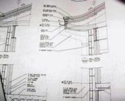


                                         details of a
                                                wall/roof section 
                                        Details. This may include
                                            bathroom fixture layouts, casework
                                            (cabinets), closet accessories, and
                                            other elements not specifically
                                            noted on other sheets. 
                                        
                                          
                                            - Elevations. These are views
                                                from the exterior, indicating
                                                the material used in exterior
                                                walls, (brick, stucco, vinyl,
                                                etc), the location of windows
                                                and doors from a side view, the
                                                roof slopes, and other elements
                                                visible from the exterior.


                                          - Structural plans. The structural
                                              plans usually are numbered
                                              beginning with "S", as in "S
                                                001" These plans include
                                              reinforcement, foundations, slab
                                              thicknesses, framing materials,
                                              (lumber, concrete pilasters,
                                              structural steel, concrete block,
                                              etc.) 


                                            - Foundation plan. This sheet will
                                                show the size, thickness, and
                                                elevation of footings (footers),
                                                with notes regarding the
                                                placement of reinforcing bars
                                                (rebar). It will note locations
                                                for anchor bolts or weld plate
                                                embeds for structural steel, and
                                                other elements. A footing
                                                schedule is often shown on the
                                                first sheet of structural notes,
                                                as well as notes regarding the
                                                reinforcing requirements,
                                                concrete break strength
                                                requirements, and other written
                                                statements for structural
                                                strengths, and testing
                                                requirements.
 
                                             
                                            - Framing plan. This will
                                                indicate the material used for
                                                framing the building. This may
                                                include wood or metal studs,
                                                concrete masonry units, or
                                                structural steel.
 
                                             
                                            - Intermediate
                                                  structural framing plans. These are used
                                                for multistory construction,
                                                where each level may require
                                                support columns, beams, joists,
                                                decking, and other elements.


                                          - Plumbing plan. Plumbing drawing
                                              pages are numbered beginning with
                                              "P". These sheets will show
                                              the location and type of plumbing
                                              incorporated in the building. 


                                            - Plumbing rough-in. This sheet will
                                                show the location of pipes which
                                                are to be "stubbed up" to
                                                connect the plumbing fixtures to
                                                water supply, drain/waste, and
                                                vent systems.
 
                                             
                                            - Plumbing floor
                                                  plan.
                                                This sheet will show the
                                                location and type of plumbing
                                                fixtures, as well as the route
                                                pipes will be run (overhead or
                                                through walls) for potable water
                                                and drain, waste, and vents.


                                          - Mechanical drawings. Mechanical pages
                                              are numbered beginning with "M".
                                              This sheet (or sheets) will show
                                              the location of HVAC (heating,
                                              ventilation, and air conditioning)
                                              equipment, duct work, and
                                              refrigerant piping, as well as
                                              control wiring.
 
                                           
                                          - Electrical plan. The electrical
                                              drawings are numbered beginning
                                              with "E". This sheet
                                              (sheets) shows the location of the
                                              electrical circuits, panel boxes,
                                              and fixtures throughout the
                                              building, as well as switch-gears,
                                              sub-panels, and transformers, if
                                              incorporated in the building.
                                              Special pages found in the
                                              electrical plan pages may be "riser"
                                                details, showing the
                                              configuration of power supply
                                              wiring, panel schedules,
                                              identifying specific breaker
                                              amperage and circuits, and notes
                                              regarding types and gauges of
                                              wires and conduit sizes.
 
                                           
                                          - BMP (Best
                                                Management Practices) drawings, or
                                              environmental plans. This sheet
                                              will indicate protected areas of
                                              the site, erosion control plans,
                                              and methods for preventing
                                              environmental damage during
                                              construction. There may be details
                                              in the BMP drawings showing tree
                                              protection techniques, silt fence
                                              installation requirements, and
                                              temporary storm water retainer
                                              measures. The requirement for a
                                              BMP plan originates under the
                                              environmental protection
                                              department of your local, state,
                                              or national governing authority.


                                           Step2: 


                                          - Locate
the
                                                element of construction you are
                                                reviewing to implement a portion
                                                of your work. If you are
                                              laying out the location of the
                                              building, you will first look at
                                              the site plan for location of
                                              existing buildings, structures, or
                                              property lines so you have a
                                              reference point to begin measuring
                                              to your building footprint. Some
                                              plans simply give a coordinate
                                              grid position using northings and
                                              eastings, and you will need a
                                              "total station" surveyor's transit
                                              to locate these points. Here are
                                              some example steps for laying out
                                              a building foot print from
                                              architectural plans. 


                                          - Lay out your
                                                building
                                              on the site by either the above
                                              referenced plan or the
                                              measurements given on the site
                                              plan. Measure to locations,
                                              preferably corners, on one side of
                                              the building, and check for any
                                              "checkpoints" to verify the
                                              accuracy of your layout. If you
                                              cannot absolutely establish an
                                              exact building line, you may have
                                              to suppose the location is correct
                                              and continue. This is widely
                                              accepted in cases where the site
                                              is very large, allowing for
                                              tolerance, but on a crowded lot or
                                              site, the location must be exact.
 
                                           
                                          - Establish the
                                                elevation
                                              you will work from. This may be a
                                              height relative to a nearby
                                              roadway, or an elevation
                                              determined from sea level. Your
                                              site plan or architectural floor
                                              plan should have a bench mark(a
                                              bench mark refers to some item,
                                              such as a manhole lid or survey
                                              way point with a known elevation)
                                              elevation or a "height above
                                              existing grade" as a starting
                                              point.
 
                                           
                                          - Use your plan to
                                                measure the location of each corner of
                                              the building, including offsets.
                                              Remember what exact element of
                                              construction you are using for
                                              your layout. You may mark an outside
                                                wall line, a foundation
                                                line, or a column line,
                                              depending on the type of
                                              construction and the most
                                              practical element for making
                                              subsequent measurements. For
                                              instance, if you are building a
                                              structural steel building with
                                              I-beam columns which require
                                              setting anchor bolts to
                                              secure them, you may begin your
                                              building layout with the center
                                              line of these columns, where if
                                              you are building a wood-framed
                                              residential structure with a
                                              monolithic slab floor, the edge of
                                              the slab would be your best choice
                                              for the initial layout.


                                           Step 3:
                                        
                                        
                                            Reference
the
                                              description of various sheets to
                                              find an element of construction
                                              you are going to use in the work
                                              you will perform. Plumbers use
                                            the Architect's
                                            floor plan to locate walls so the
                                            pipes they stub up will be concealed
                                            inside the wall cavity when the
                                            building is constructed, then use
                                            their plumbing floor plan to find
                                            out what types and sizes of pipes
                                            are required to service a particular
                                            fixture. 
                                        
                                           Step 4:
                                        
                                            Use
                                              the dimension scale where
                                              measurements are not provided.
                                            As a rule, architectural plans are
                                            drawn to a "scale". An example would
                                            be, 1 inch equals 10 feet (1"=10'),
                                            so measuring between to walls on the
                                            plan sheet means for each inch, the
                                            distance is 10 feet. A scale rule
                                            will make this much easier, but be
                                            careful to match the rule scale to
                                            the plan's scale. Architects
                                            often use a scale of fractions, such
                                            as a 1/32 scale, engineers usually
                                            use an inch per foot scale. Some
                                            plans or details are not to scale,
                                            and should be marked "(NTS)". 
                                        
                                           Step
                                                5:
                                                      
                                        
                                        Read
                                              all notes on a page. Often a particular
                                            element has special considerations
                                            which are more easily described
                                            verbally than drawn, and notes are a
                                            tool the architect
                                            will use to illustrate them. You may
                                            see a table of notes on the side of
                                            a sheet, with numbers identifying
                                            the note location on the plan (a
                                            number with a circle, square, or
                                            triangle around it) and a
                                            corresponding numbered statement
                                            describing the situation on the side
                                            of the sheet. 


                                           Step 6:
                                        
                                            
                                            Learn
                                              to recognize the different types
                                              of lines the architects
                                              and engineers may use. You
                                            should have a specific keynote table
                                            for section of plans, and this will
                                            provide information on the
                                            abbreviations, symbols, and specific
                                            lines used in each section of the
                                            plans. An example would be in the
                                            electrical plans, a circuit may have
                                            the "home run" "leg" (the
                                            wire going from the first junction
                                            box in a circuit to the panel box
                                            (the power source) highlighted or in
                                            darker ink than other circuits, and
                                            exposed conduits may be indicated by
                                            a solid line, and concealed conduits
                                            by a dotted or broken line. Because
                                            there are many different line usages
                                            indicating different type walls,
                                            piping, wiring, and other features,
                                            you will have to see individual plan
                                            page "key notes" to understand them. 
                                          
                                        
                                           Step 7:


                                            Use
                                              a "Builder's" calculator to add
                                              dimensions when determining
                                              distances on your plans. These
                                            are calculators which add feet and
                                            inches, fractions, or metric
                                            measurements. Often, an architect
                                            will not give a measurement to a
                                            specific plan item, from a baseline
                                            such as the "'OBL" (outside
                                            building line), so you will need to
                                            be able to add the distances each
                                            feature which has a measurement
                                            provided, to get the total distance.
                                            An example would be finding the
                                            center line of a bathroom wall to
                                            locate the potable water pipe stub
                                            up. You may have to add the distance
                                            given from the OBL to the living
                                            room wall, then the distance to a
                                            hallway wall, then across a bedroom,
                                            to the bathroom wall in question.
                                            This might look like (11' 5)
                                                + (5' 2") + (12' 4") = 28' 11". 


                                           Step 8:
                                        
                                             Use
                                              CAD (Computer Assisted Design)
                                              building plans. If you have a
                                            set of architectural plans in an
                                            electronic form, as on a CD, you
                                            will need a version of the original
                                            "cad" program which created it to
                                            open the files. "AutoCAD" is a
                                            popular, but very expensive,
                                            professional design program, and the
                                            designer will usually include a
                                            "Viewer" on the disc which you can
                                            install on your computer to view
                                            files, so that actual plan pages
                                            appear on your screen, but without
                                            the full program, you cannot
                                            manipulate design components or
                                            change the drawings. 
                                        Step 9:
                                                   
                                            
                                            Learn
how
                                                to handle architect's plans.
                                              These sets of documents are often
                                              very large sheets, about 24" X
                                              36", and full construction sets
                                              may include dozens, or hundreds of
                                              pages. They are either bound or
                                              stapled on the left edge, and
                                              allowing them to be torn from the
                                              bindings, ripped apart by
                                              mishandling, laid out in the sun
                                              to fade the ink, or left in the
                                              rain can make them difficult to
                                              use. These documents can cost
                                              hundreds of dollars (US) to
                                              replace, so try to protect them,
                                              and have a flat, wide, protected
                                              work surface to unroll and read
                                              them on. 
                                        Step 10:


                                              Remember that the
                                              building plans for a project often
                                              include contract documents other
                                              than the Architect's Drawings. 
                                        Step 11:


                                              Specifications are usually printed
                                              and kept in a binder, and they
                                              list descriptions of methods and
                                              materials used in the project, as
                                              well as testing methods, quality
                                              control information, Geo-technical
                                              data, and other information useful
                                              in building the project. 
                                        Step 12:


                                              Look for notes and
                                              symbol referring to "alternate bid
                                              items" and "addendums". These
                                            may indicate portions of work which
                                            are incorporated in the Architect's
                                            drawings, but not in the builder's
                                            contract to construct, supply, or
                                            install. "NIC" is an abbreviation
                                            for Not In Contract, which means a
                                            certain item will be put in a
                                            certain place by the owner after the
                                            project is finished. "OFCI" or
                                            "GFCI" (Owner Furnished, Contractor
                                            Installed, or Government Furnished,
                                            Contractor Installed) indicate the
                                            item is supplied by the customer,
                                            but installed by the contractor.
                                            Read and understand all
                                            abbreviations used in your plans. 
                                        Contact us at: chin178@gmail.com
                                              
                                              www.ArchitectChin.com 


                                                    All Images are Copyrighted
                                                    by www.ArchitectChin.com
                                                    1995 - 2025 
                                               
                                                                                
                                                  Designed by Chin Architect 


                                     | 


                           | 


                   |